

Fun With Crystal Oscillators: Part 3
In Fun With Crystal Oscillators: Part 1 we discovered how to use a crystal oscillator to generate an RF signal. Â In part 2 we added an audio transformer to modulate the signal to create a low powered AM radio station. Â In part 3 we will scrap the audio transformer and use an LM386 IC to make things work more efficiently.
The circuit presented in part 2 works, but its shortcomings are seen quickly. Â I had problems getting the audio to sound clean and loud just using an audio transformer. Â Using an LM386 and a few extra parts will add a lot more efficiency to your station.
The LM386 is a common integrated circuit that acts as an audio amplifier. Â These little things can actually make some pretty big sound. Â I've used them in a few projects, like my Arduino doorbell.
Pin diagram for the LM386 IC
The most important pins are 3 (your audio input), 6 (your voltage input), and 5 (your audio output). Â Pins 2 and 4 go to ground. Â A capacitor between 1 and 8 will increase your audio gain (a.k.a. louder volume). Â Pin 7 with a capacitor can be used to clean up the audio output. Â Checkout the datasheet for more information.
The transmitter circuit feeds the signal output of the LM386 into the crystal oscillator to modulate the RF signal. Â A few capacitors and a resistor are added to the LM386 as per its datasheet specs and to clean up the audio signal.
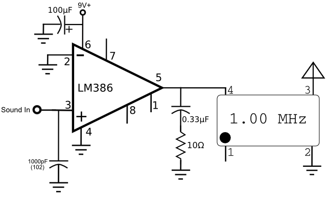
If you don't have all the parts for the lm386 portion of the circuit, don't worry. Â The only part here that really matters is the capacitor on pin 3, which helps increase the audio quality. Â The capacitor and resistor on pin 5 don't seem to make much of a difference, but I left them in because they are part of the standard lm386 build out from the data sheet. Â The capacitor on pin 6 where the voltage is input, smooths power fluctuations, but with a 9v battery input you don't need to worry about this too much.
After you power up your circuit and plug it into an audio source (like your phone), tune your radio to 1000 kHz and take a listen. Â If all went well you should hear music playing, and it should sound a lot better than the circuit in part 2. Â If the audio is distorted, try lowering the input volume on your phone / mp3 player. Â The distortion is overmodulation.
Boosting your range
First off, this is not a high power transmitter by any stretch of the imagination. Â As I demonstrated in part 1 you can actually get some decent RF watts output by pumping in a high amp 12v power source, but your oscillation stability will quickly vanish and so will your signal. Â A 9v battery is ideal for this circuit, but it will barely show any movement on a watt meter, meaning you are putting out a puny signal. Â This is good though, because if you managed to really boost power with this circuit, you would probably get a knock on your door from the FCC at some point.If you want to extend the range of this transmitter you need two things, a better antenna, and better ground plane.
For the antenna, all you need is more wire. Â Using an antenna that is a foot in length will probably get your signal across the room. Â If you use 10 or 12 feet of wire this will really help beefing up your range, especially if you can elevate the wire a bit.
The longer antenna alone isn't enough though to get real range.  For this you will also need a ground plane.  For the ground plane, connect to the circuit ground a similar length of wire that was used for the antenna.  This wire is often referred to as a counterpoise and in effect creates a balanced antenna.
With the addition of the balanced antenna system, you may be able to extend your signal down the street, and it still should be legally covered under Part 15 (see part 1 for more details). Â Experiment with different lengths of wire and different heights to see how far you can get your little signal to go!
Here's a vine showing the circuit in action:
Read more:
Fun With Crystal Oscillators: Part 1
Fun With Crystal Oscillators: Part 2
Posted: Jul 01, 2013
Keyword tags: basicscrystal oscillatortransmitterlm386AM radioAM transmitter

