Make Your Own Rocket Radio with the TA7642
When my mom was a kid she owned a rocket radio, which was type of TRF crystal radio that was a popular kids toy in the 50's and 60's.  As a kid one of my favorite past times was tuning the AM dial on my favorite radio (after bedtime); it turns out she did the same as a kid with her rocket radio, pulling in stations around the north east US corridor.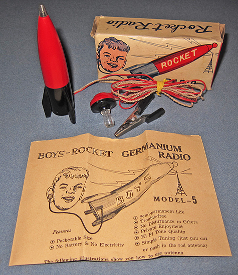
You can find vintage rocket radio's on eBay, but as a Christmas present I decided to make an updated model for her using the TA7642 IC.
The TA7642 is a complete AM radio receiver on a chip.  With a few extra components, you can have a fully functional TRF radio receiver in the palm of your hands.  In fact, there's a whole community of people that build use these types of IC's to build matchbox radios!
The TA7642 is an updated version of the MK484 chip, which is an updated version of the ZN414, which was popular decades ago.  Both the MK484 and ZN414 are harder to find now, but the TA7642 can be had relatively easy on eBay and other places on the net.  There is one store I've found that sells the MK484, but I haven't ordered from it personally.
Both the TA7642 and the MK484 chips are packaged in a TO-92 case, making it look like a transistor.
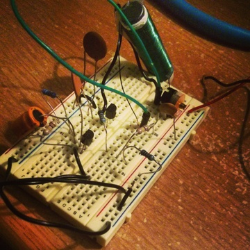
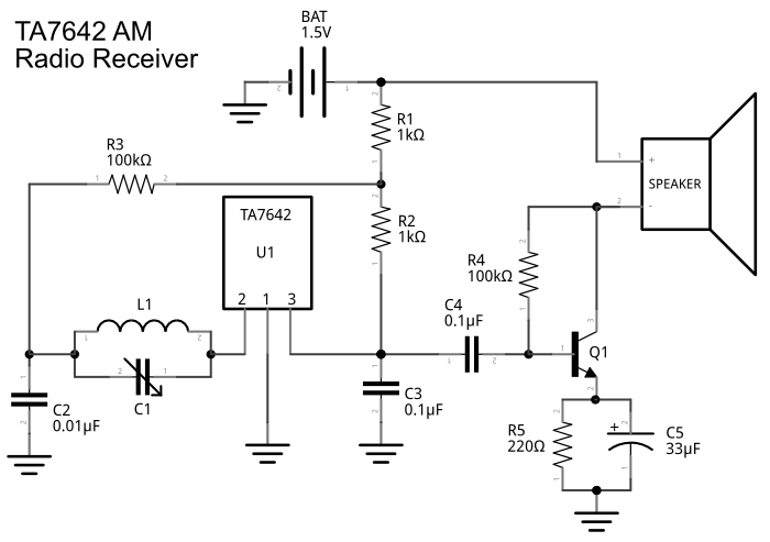
The following schematic will turn this chip into a functional radio.
Part list
| U1 | TA7642 |
| Q1 | 2n3904 |
| L1 | (see notes) |
| C1 | (see notes) |
| C2 | 0.01uF |
| C3 | 0.1uF |
| C4 | 0.1uF |
| C5 | 33uF |
| R1 | 1k ohms |
| R2 | 1k ohms |
| R3 | 100k ohms |
| R4 | 100k ohms |
| R5 | 220 ohms |
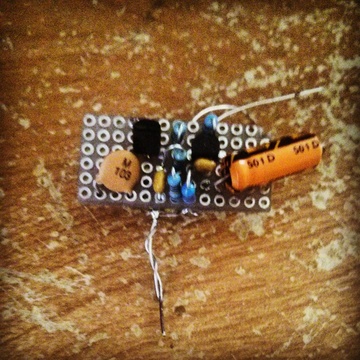
The first stage of the circuit revolves around U1 (the TA7642 chip) and tunes the resonant frequency to a particular AM broadcast station.  The output from this stage is too weak to power a speaker or headphones, although if you connected the output to an oscilloscope you will see the modulated AM carrier (you might be able to hear something directly from pin 3 on U1 if you live by strong local AM stations).  To actually hear the signal as audio, the second stage of the circuit surrounding Q1 will boost the signal.
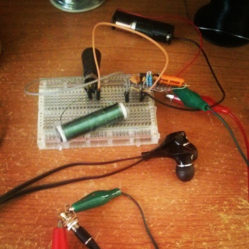
The inductor L1 is essentially a loop stick antenna.  I used a two inch ferrite rod (actually I glued two inch long pieces together), and wound 26 gauge magnet wire around it as many times as possible.  I didn't end up counting how many turns I wound, but I estimate it was somewhere around 70 turns.  When you are building your loop stick, you don't really need to be concerned about the exact number of turns or exact size or properties of ferrite rod.  Yes, there are calculations to determine the inductance for number of turns if you know the ferrite material type, but with a little experimentation you will have a pretty decent antenna quickly.  Try to get at least 50 or 60 turns on your rod.  Probably 60-90 turns is ideal for the MW AM broadcast band, but again it really depends on the rod type, length, and material.  You can get ferrite rods on Amazon and a number of other places.
C1 is a variable capacitor. Â The larger the value, the more range you can tune. Â I used a 0-100uF variable capacitor I picked up at Dayton, particularly for its small size. Â Even with this limited range, it allowed me to tune over the majority of the AM broadcast band.
And, tune in stations it does! Â I was able to pull in a half dozen AM stations with relative ease here in Pittsburgh and a few others depending how I oriented the loop stick antenna and how fine a touch I had with the tuning dial.
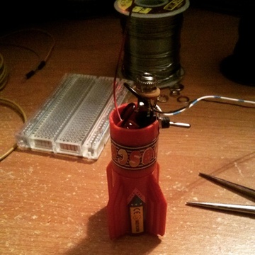
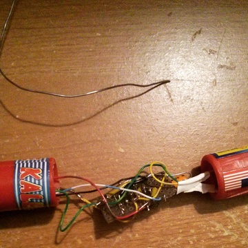
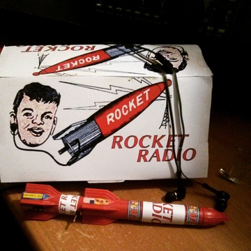
I assembled the radio inside a few plastic rocket kaleidoscope's I bought from Amazon.  Since the antenna took up about one full rocket, and the battery took up another full rocket, I ended up joining three of them together and doing a little body modification to make the body into one large rocket.  I affixed the variable capacitor to a rubber stopper I picked up at Home Depot and glued it inside the top, so you can tune the radio by twisting the top of the rocket.
Completed product!
Posted: Jan 25, 2015
Keyword tags: rocket radiota7642mk484zn414AM radioschematicmake a radio
Recent Posts
Sticky Posts
shortwavetransmitterqrpschematicAM transmitterelectronics500mWarrlfield daycwradio operatingdayton hamventionham radiocrystal radiosteampunkbasicsmatchbox radio1N34 dioderocket radiota7642mk484zn414AM radiomake a radio


