Ten Minute Transmitter
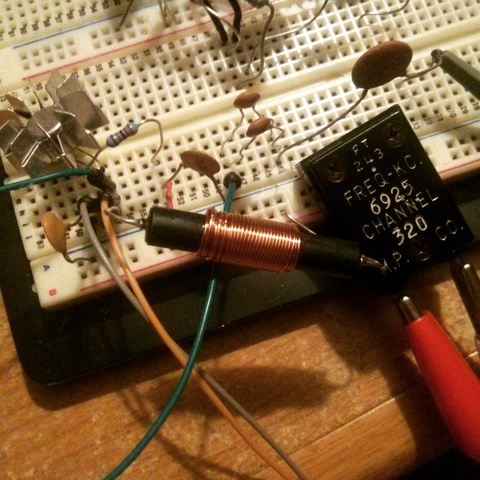
Last weekend I was browsing the internet for radio circuits and came across an interesting design I've never seen before, nicknamed the Ten Minute Transmitter.  The design apparently originated in 1996 in an amateur radio club QRP publication.  The name originates since the original author claimed he built this transmitter and make a QSO with it in just 10 minutes time.  Impressive!I didn't set a stopwatch to time myself, but I can tell you that I was able to slap this rig together on a breadboard and tune it up very quickly.  There are no coils to wind (unless you want to); it tunes a wide range of crystal frequencies, and it outputs an easy 500mW AM signal.  I had three crystals on hand, and was able to load up frequencies 6925 kHz, 14322 kHz and 28266 kHz without problem.
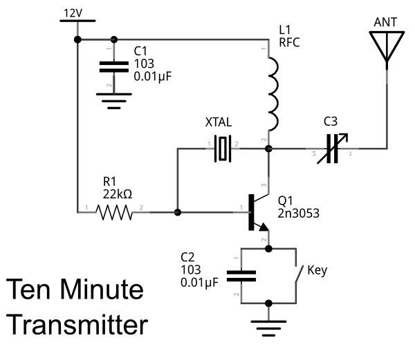
Here's the schematic:

Essentially the transmitter is a crystal oscillator that can be loaded with a 50 ohm antenna. Â I didn't calculate the output impedance to the antenna, but it loaded up on my dummy load without problem.
For the RFC (RF choke) you can use something off the shelf, like the Radio Shack 100 uH RF choke, or wind your own inductor.  I did squeeze out a little more power by winding my own 3.3 uH inductor, but it's not really necessary.  The original schematic calls for a 1000pF variable capacitor.  I didn't have any on hand with that wide of a tuning range, but did have one that probably peaks at around 400pF.  The larger variable capacitor would probably optimally tune a wider variety of crystals, but I didn't have any problems using a smaller value.  If you don't have a variable capacitor handy, try stacking a few ceramic disk capacitors in parallel together.  I used a variable capacitor for the initial build, but found adding two disc capacitors that totaled 200pF worked well with my 6925kHz crystal.
The 2n3053 (Q1) can be replaced with either a 2n2222 or 2n2219 transistor, and probably other metal can transistors. Â I saw no difference in power output or signal quality between any of these transistors. Â Whichever you choose, the transistor will need to be heatsinked, as it does heat up a bit. Â Don't use a standard 2n3904. Â I plugged one in to see what would happen and lots of smoke emerged!
If you close the key (or just use a piece of wire in place of a morse code key) the transmitter will generate a continuous AM signal. Â On a radio tuned to the frequency in AM mode, you will hear silence instead of the usual radio static. Â If you tune to the signal using LSB, USB, or CW modes you will instead hear a tone.

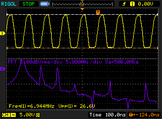
The waveform generated is close to a sine wave, but does have some distortion, which means it generates harmonics.  The harmonics can be filtered out with a low pass filter to obtain a clean transmit signal.

My usual warnings about experimenting with radio circuits hold.  Only transmit on frequencies you are legally able to use, and always experiment with your antenna output connected to a dummy load or an appropriate size 50 ohm resistor.
I've already done some additional experimentation with this design and have some improvements, including a stage to amplify the signal, which I'll write about soon.
Posted: Feb 25, 2016
Keyword tags: shortwavetransmitterqrpschematicAM transmitterelectronics500mW
Recent Posts
Sticky Posts
shortwavetransmitterqrpschematicAM transmitterelectronics500mWarrlfield daycwradio operatingdayton hamventionham radiocrystal radiosteampunkbasicsmatchbox radio1N34 dioderocket radiota7642mk484zn414AM radiomake a radio


