Essential Equipment: Measuring RF Circuits with an Oscilloscope
I recently picked up a new tool for the workbench, a Rigol DS1102e oscilloscope! Â An oscilloscope has been on my wish list for a while, as it is an essential tool for electronics design and debugging. Â They are also extremely useful for measuring and tuning RF circuits.
To present how an oscilloscope is useful for RF transmitter design, I will measure some of the circuits we have previously explored. Â A mini review of the scope is also included below.
First up is the basic crystal oscillator transmitter. Crystal oscillators produce a square wave, which generates odd harmonics.  To measure the oscillation, build the circuit, and connect your probe to pin 3 on the oscillator and the ground probe to ground or pin 2.  You should see something like this: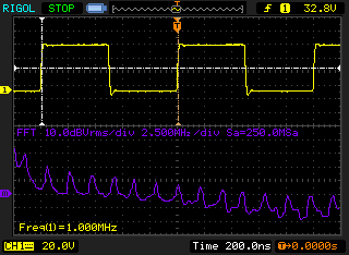
The top reading in yellow is showing the signal generated by the crystal oscillator, while the bottom in purple is showing the Fast Fourier Transform (FFT) of the signal. Â The signal isn't a perfect square wave, but it's close enough. Â You can see the frequency measurement at the bottom of the screen showing 1.00 MHz. Â The FFT is useful for analyzing harmonics generated by the signal, and you can clearly see the odd harmonics generated by the square wave.
Next, we will look at some measurements from the Michigan Might Mite transmitter. Â For the first measurement we will look at the waveform inside the oscillator stage of the circuit. Â Hook the probe to one leg of the crystal and the ground probe to ground. Â The waveform will look like this:
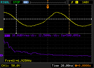
You can see that the oscillator is generating a sine wave at 6.925 MHz, exactly as it should (because I'm using a 6.925 MHz crystal). Â The sine wave isn't perfect, but it's pretty good. Â You can also see that it produces a few harmonics, by referring to the purple FFT. Â By tuning the circuit with the variable capacitor you will see the sine wave change in amplitude and shape. Â When it moves out of the proper range, the radio signal will drop out. Â In general, you will want to tune the circuit to have the highest amplitude and/or the most clean waveform.
Hooking the probe to the transmitter output is where things get really messy. Â Be careful hooking up your scope to a transmitter antenna input! Â This is only recommended for low power transmitters, as you can blow up your scope if the voltages range too high!
Connect the transmitter to a dummy load, and connect your probe to the dummy load. Â For this test I'm just using a 50 ohm resistor as a dummy load (a 47 ohm resistor will work fine too). Â The wave form generated looks like this:
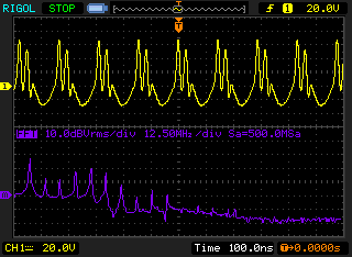
As you can see, the waveform isn't clean at all, and looking at the FFT we can see many powerful harmonics that are nearly as strong as our desired output frequency! Â These harmonics are a design limitation of the Michigan Mighty Mite that can be cleaned up with a low pass filter
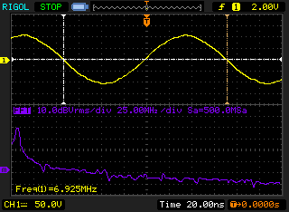
For the final measurement, I connected the transmitter to my 40 meters low pass filter, connected the filter to a dummy load, and measured the waveform again, by connecting my probe to the dummy load resistor. Â The wave form generated is a very clean sine wave! Â Looking at the FFT there is one clean spike at 6.925 MHz, which means the low pass filter is working perfectly, eliminating all the harmonics generated in the AM signal!
First impressions and quick review of the Rigol DS1102e
Since many good reviews of the Rigol DS1102e (and it's 50 MHz companion, the DS1052e) are available on the web, I didn't want to write a full out review. Â But, I do want to jot down some first impressions.In short, I'm really happy with this scope! Â I purchased it from Amazon for less than $400, which is a great bargain for all its functionality. Â If you need a scope that ranges higher than 100 MHz, or has more than 2 channels, or has other fancy functionality -- be prepared to shell out a few thousand dollars. Â For electronics hobbyists and makers, this scope will get you what you need.
When I purchased it, I actually didn't know it computed FFT's of the waveform. Â This is hands down my favorite feature so far, as it is so essential to transmitter design and testing. Â Typically, you would need a spectrum analyzer to measure harmonics, which are quite expensive. Â The FFT will do this for you, making it very excellent feature.
Measuring the FFT harmonics is as simple as scrolling the x-axis toward the center of the screen, until you reach the visual spike. Â Unless I haven't found a hidden setting, it appears that you can only move the x-axis of the FFT by units of 200 kHz, meaning it's difficult to get an exact frequency reading of the harmonic, but it should get you close enough, and the exact number can be found on a calculator with simple multiplication.
In general, I've found the menus easy to work with, and there is a lot of great functionality inside, like the ability to take screenshots and save them to a USB stick.
There are two annoyances I have that I dock a few points for:
- The scope didn't come with a full instruction manual. Â It did ship with an abbreviated quick start manual, and the full manual is available online, but it would have been nice if the full manual was included in the box.
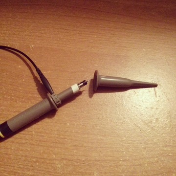
- The hook leads that slide onto the probes don't sit tight and are prone to fall off.  I sort of fixed this issue by placing a small square of white electrical tape on the probe to make it tighter.  It seems to work well enough, although it still falls off from time to time, and it sometimes sticks open because of the tape.
EDIT 5/29/2014: I recently found out that the reason the leads were falling off the probes was because they weren't snapped in. Â I was afraid I would break them by using too much force, and never realized that they do indeed snap in place! Â Problem solved!
So, there you have it. Â I recommend the Rigol DS1102e oscilloscope to anyone looking for a nice quality unit for their home. Â The minor annoyances are easily outweighed by its great price point and functionality, and this unit has some great features for radio electronics hobbyists.
Posted: Sep 09, 2013
Keyword tags: electronicsmeasurementRFoscilloscopeharmonicsessential equipmentcrystal oscillatortransmitter


