An LM386 Powered Crystal Radio in an Altoids Smalls Tin
Last year I was designing an Arduino powered doorbell for my new home, and I reached for the trusty LM386 to build the audio amplification stage. Â But, at my new QTH (a high elevation in a major city with line of site radio towers in the distance) the LM386 was not only amplifying the doorbell tones, it was also pulling in a nearby AM radio station! Â Although this was a major annoyance while designing the doorbell, I wanted to revisit the LM386 in the future as a basic radio receiver.If you live in a location like me, then the following basic circuit may pick up the strongest local radio station, or you may hear a 60Hz buzz from your power lines, or you may hear nothing at all. Â Try it at night for the best results.
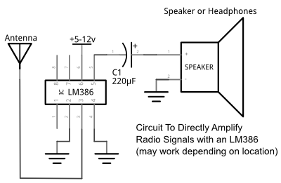
But, we can improve upon this basic circuit by adding just a few more parts, and gain better selectivity and sensitivity.
You may have heard of a crystal radio (or a crystal set), which is a simple circuit that uses a diode as an RF detector and a tuned LC (inductor / capacitor) circuit to receive radio.  It's about as bare bones as it gets for a radio receiver, and if you have a crystal earpiece, you don't even need a battery to power it.  It just pulls the radio waves out of the air and you can listen to them!
Well, I don't have a crystal earpiece, but I do have plenty of LM386 amplifiers and batteries, and from my doorbell experience, I already knew that the LM386 will amplify radio waves. Â So, I combined a basic crystal radio with an LM386 to create this basic AM radio:
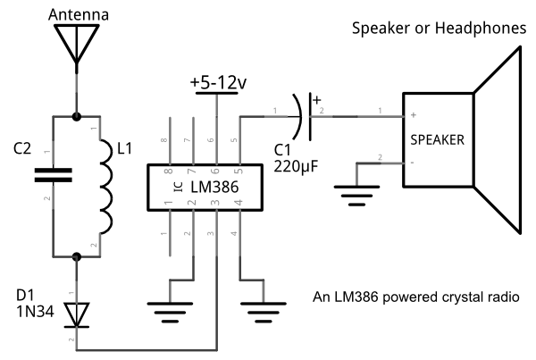
You may be wondering where the "crystal" is in this crystal radio.  It's in the diode that we are using to detect our RF signal.  Specifically, this circuit requires a germanium diode as the RF detector -- at least you will have the most success with a germanium diode.  People typically prefer to use the 1N34 diode for this application, but I didn't have any available so I used a generic germanium diode, and it worked well.  You can find 1N34 diodes easily on Amazon, eBay, etc.
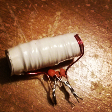
The circuit needs to be tuned to the correct range or you will hear nothing but static. Â I am using 35 turns of 24 gauge magnet wire around a ferrite rod for L1 and 1410 pF for C2 (use three 470 pF capacitors in parallel); but you will likely need to play with different values for your location. Â I took the radio with me on vacation, excited to show a friend my latest build, and it didn't work at all. Â I came back home and it worked great. Â So, optimizing for your location does matter.
You can tune the radio by adding or reducing either the L or C values (increasing or decreasing the inductance or capacitance of the tank circuit). Â I didn't have much luck tuning the capacitance with a few different variable capacitors, but tuning the inductance worked very well. Â To make my variable inductor, I took the 35 turns of magnet wire (mentioned above) and wrapped it on a thick paper form (a good use for junk mail!) that fit around the ferrite rod. Â To increase/decrease the inductance, move the ferrite rod in and out of the wire form.
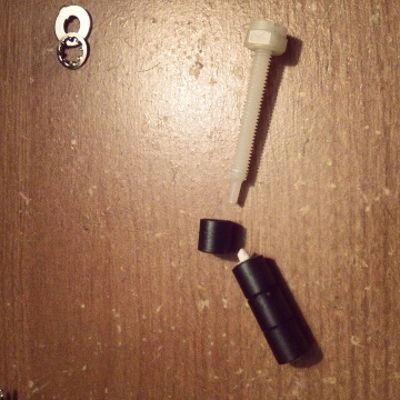
I made a ferrite bar by gluing several ferrite cores to a plastic screw that could be used to tune the inductor (by moving the bar in and out of the wire turns).
Don't be stingy with the antenna! Â I was able to pick up the strongest AM station in my area with just a foot of wire, but when I hooked it up to my outdoor long wire antenna, wow! Â I could hear strong and distinct signals while tuning.
So, how does it perform? Â Pretty well for something so simple! Â With the above circuit (on the breadboard) I was able to tune into 4 or 5 local AM radio stations. Â I was also able to pick up a local FM station by removing the LC circuit and replacing it with about eight turns of loosely wound 22 gauge magnet wire around a pencil. Â Technically speaking, you should only be able to detect AM stations with a crystal radio, but FM detection is possible via a principal called slope detection.
I was pleased enough with the performance, and soldered it up inside an Altoids Smalls case. Â Getting everything to fit in the Altoids Smalls tin was a challenge, but a fun one. Â I used a 6v type-N battery, which saved a lot of room in the case.
Here are some pictures of the completed radio:
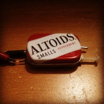
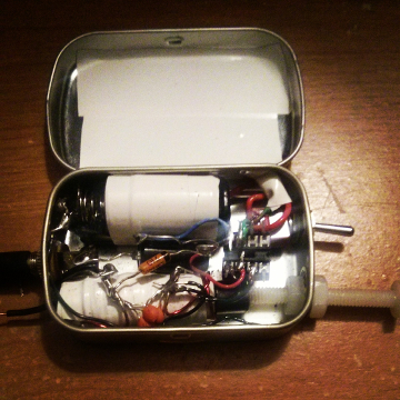
Unfortunately, the Altoids tin reduced performance of the circuit. Â The additional grounding of the metal case creating parasitic capacitance appears to be the culprit. Â It still works, but I was able to pull in more signals on the breadboard. Â The next time I build a crystal radio, I'll probably use a plastic candy case instead of a metal tin. Â But, it does work and looks awesome in the Altoids Smalls tin.
So, how does it perform? Â Pretty well for something so simple! Â With the above circuit (on the breadboard) I was able to tune into 4 or 5 local AM radio stations. Â I was also able to pick up a local FM station by removing the LC circuit and replacing it with about eight turns of loosely wound 22 gauge magnet wire around a pencil. Â Technically speaking, you should only be able to detect AM stations with a crystal radio, but FM detection is possible via a principal called slope detection.
I was pleased enough with the performance, and soldered it up inside an Altoids Smalls case. Â Getting everything to fit in the Altoids Smalls tin was a challenge, but a fun one. Â I used a 6v type-N battery, which saved a lot of room in the case.
Here are some pictures of the completed radio:


Unfortunately, the Altoids tin reduced performance of the circuit. Â The additional grounding of the metal case creating parasitic capacitance appears to be the culprit. Â It still works, but I was able to pull in more signals on the breadboard. Â The next time I build a crystal radio, I'll probably use a plastic candy case instead of a metal tin. Â But, it does work and looks awesome in the Altoids Smalls tin.
Side note: Â The size of an Altoids Smalls tin has apparently changed since the candy was originally released. Â I saw several places on the net that said that an Altoids Smalls tin could fit a 9v battery. Â The tin I picked up had a slightly different case design, and it was just slightly too small to close with a 9v battery inside. Â Of course, a regular size Altoids tin still fits a 9v battery well.
Posted: Jun 09, 2014
Keyword tags: altoidscrystal radiolm386schematic
Recent Posts
Sticky Posts
shortwavetransmitterqrpschematicAM transmitterelectronics500mWarrlfield daycwradio operatingdayton hamventionham radiocrystal radiosteampunkbasicsmatchbox radio1N34 dioderocket radiota7642mk484zn414AM radiomake a radio


