

More Fun With Crystal Oscillators: Amplifying RF
Edit 10/30/2014: I posted an improved version of this circuit in another post. Â Take a read through this post, but head over and read the new post for the better design.
The basic crystal oscillator transmitters we covered over a few posts (post 1, post 2, post 3) are a great way to get your feet wet in radio electronics.  (Never work on electronics with wet feet, unless you like fried hair!) But, from a practical perspective, these transmitters aren't all that useful for anything more than creating a mini home AM radio station.
When I first started experimenting with these basic transmitter circuits, the first thing I wanted to do (after getting it working) was to boost the signal. Â At the time, I couldn't find anything on the internet to help me in this quest (at least not anything that was basic enough for me to understand). Â So it's with some personal satisfaction that I can post this now. Â I also know now why this design is terrible, and should never be used; I'll explain below.
By increasing the RF output with a simple amplifier, the crystal oscillator can be the basis of a useful communications tool.
Introducing the IRF510, a power MOSFET in a handy TO-220 case, which makes it easy to heat sink. Â The IRF510 is often used to amplify signals, and can be used as an audio amplifier as well as an RF amplifier, and is really common to find. Â Radio Shack stocks them, and so does pretty much every other component source.
Using the IRF510, I was able to get 5 watts of RF with the following circuit: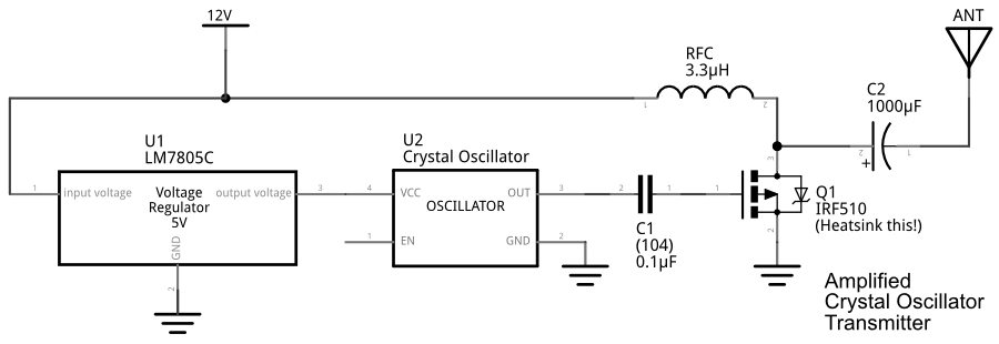
Since most crystal oscillators prefer an input voltage at around 5 volts, I'm using an LM7805C voltage regulator to step the voltage fed into the crystal oscillator to 5v, while the IRF510 is receiving the full 12v. Â Capacitor C1 buffers the output signal that is fed into the amplifier. Â The IRF510 is fed 12v through an RF Choke. Â The value of the RFC is pretty arbitrary, and a wide range will likely work. Â I had a 3.3uH RFC that I wound for the colpitts oscillator post, and it worked well. Â The IRF510 output is fed into a capacitor, which is fed into the antenna -- or in this case a dummy load.
You really need to heat sink the IRF510, and use some thermal paste on the heat sink to ensure a good bond. Â I recommend this heat sink. Â This part gets hot quickly! Â If you aren't careful you may burn your fingers (I did a few times), and it could very well cause a fire if the heat cannot be dissipated. Â Be careful.
By using a 1000 uF capacitor for C2 I was able to get 5 watts of RF power out of the circuit. Â By using a 470 pF capacitor I got 2 watts, and a 470 uF capacitor gave me 4 watts. Â There are limits to how much amplification you can produce, of course. Â I tried a 2200 uH capacitor and got about 5.5 to 6 watts. Â Basically, as the capacitance increases, we are able to store more energy, up to the limits that the circuit can produce.
Here's an image of the circuit on the oscilloscope: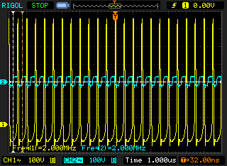
Wow, look at that signal! Â The blue line is the square wave produced by the crystal oscillator, and the yellow is the amplified signal!
Here it is on the breadboard: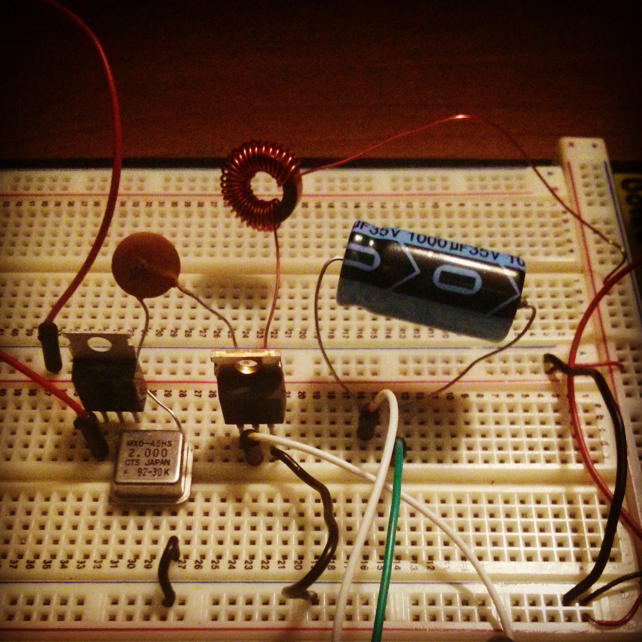
Disclaimer
Now a few words of caution:  This circuit is extremely illegal to use, unless you connect the antenna output to a dummy load.  Seriously, this is one that you don't want to put on the air.  If you remember back to our previous discussions, the crystal oscillator produces a square wave, which produces odd harmonics.  This wasn't much of an issue when we were putting out a few milliwatts of power, but with 5 watts of power these signals can travel, and you would be polluting a large swath of radio frequencies.  The only way to use this transmitter legally, would be to: 1) Filter out the harmonics, 2) Place the filtered signal in one of the ham radio bands, and 3) Have an appropriate ham radio license that would allow operating privileges on said frequency.  You don't want the FCC knocking on your door because you were interfering with a local EMS dispatch frequency.
As usual, I advocate safe experimentation. Â Build stuff and have fun, but use a dummy load when building and testing transmitters, and never put a transmitter on the air unless you are sure it will operate how you expect, within the bounds of the law.
Additional reading:
Fun With Crystal Oscillators: Part 1
Fun With Crystal Oscillators: Part 2
Fun With Crystal Oscillators: Part 3
Edit 10/30/2014:Â A better version of an amplified crystal oscillator transmitter!
Posted: Jul 27, 2014
Keyword tags: crystal oscillatoramplifiertransmitterschematicirf510

