

A Mighty Simple Shortwave Transmitter
How many parts does it take to make RF? Â Seven if you're the Michigan Mighty Mite!
The Michigan Mighty is the name given to one of the most simple HF (a.k.a. shortwave) transmitters designed, which makes it an interesting project for both novices and hobbyists learning about RF fundamentals.
The history of this transmitter is a bit cloudy.  It's generally credited to two hams: Ed Knoll, W3FQJ and Tom Jurgens, KY8I, but information about its origins is difficult to track down.  One person on qrz.com claims to have found the exact schematic in an old magazine from 1977.  This usenet post from 1994 has also been found.  Another site discusses the origin as an article written by W3FQJ (no mention of the article name or publication) and was featured later in The Five Watter’, a newsletter produced by the Michigan QRP Club.
In general it doesn't really matter where it came from, so let's thank W3FQJ and KY8I and get on to building the transmitter!
This little circuit can put out about 1/2 a watt RF on 160, 80, 40 or 30 meter amateur radio bands (or any frequencies in between and close by, including the infamous shortwave pirate radio band found under the 40m ham radio band).  The core of the design is a crystal controlled oscillator, which is fed into an RF output transformer, or tank coil.
Without any modifications, the basic design will allow for CW operation, but I will cover a few enhancements in subsequent posts that will allow for audio modulation and filtering.
The schematic is as follows: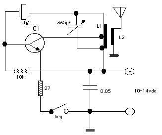
Component list:
| XTAL | This is your crystal that should be within one of the frequency ranges discussed above.  If you don't have a crystal on hand, look at the links I mentioned here. | ||||||||||||||||||
| Q1 | Use a 2n2219, 2n2222a, or 2n3053 transistor. Â Others may also work. Â I suggest using a TO-39 metal can style transistor, because this gets hot. Â If possible add a heat sink to it. Â If no heat sink is available, I've heard of people using an alligator clip attached to the top. | ||||||||||||||||||
| 365 pF variable capacitor | Try one of the models I mentioned here if you don't have one on hand.  Worse case, just take a few regular capacitors and place them in parallel until you are happy with the RF output.  A variable capacitor is necessary though for optimal tuning of the circuit. | ||||||||||||||||||
| 10k ohm resistor | A very common value | ||||||||||||||||||
| 27 ohm resistor | A less common value, but easy to find.  Or you can do what I did and chain three 10 ohm resistors in series.  Whatever choice you make, the resistor value should be rated for at least 2 watts, so a single 2+ watt 27 ohm resistor works or a few 1 watt 10 ohm resistors will also work. | ||||||||||||||||||
| 0.05 uF capacitor |
A common value. Â If you don't have the correct value, chain a few lower value caps in parallel. EDIT 2014-06-04: Previously/incorrectly listed capacitor as 0.05 pF. Â The correct value is 0.05 uF. |
||||||||||||||||||
| L1 / L2 tank coil |
|
Creating the Tank Coil
The tank coil diameter should be around 1.25". Â If you have a spare prescription bottle or film canister, either will work well as an inner form to wind your wire around. Â Remember to use a non-conductive form (e.g. plastic or wood).
Use #20 - #22 gauge magnet wire to construct your coils.  If you don't have any, Radio Shack sells magnet wire, and you can pick it up on Amazon and a number of other places.
The tank coil essentially is comprised of two inductors (L1) that work within the oscillator circuit collecting magnetic energy. Â This energy is transferred in the form of RF to L2Â at a 50 ohm impedance.
To wind the tank coil, start with L1, winding clockwise to the number of turns until the tapped at number.  Create the tap by making a loop an inch long, twisting it a few times to hold it in place.  Continue winding clockwise until you reach the total number of turns.  Sand off the enamel from each end of L1 and on the center of the tap.  I usually use a lighter to burn the enamel a little then use an X-Acto knife to scrape it off.  Whatever your technique, remember that it needs to make good electrical contact in your circuit.  Tape L1 together when you are satisfied.
Here is an image of what L1 looks like wound on a form:
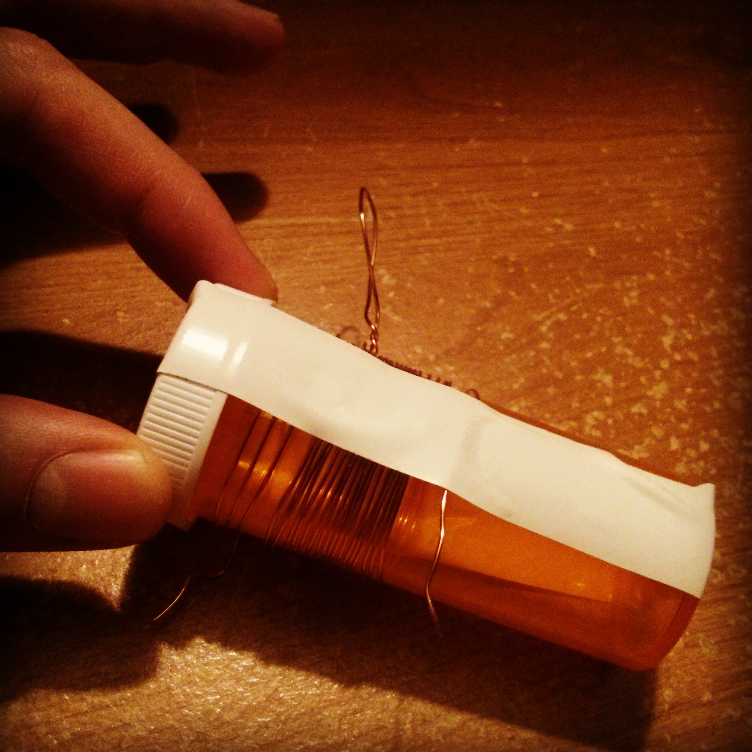
The inch long wire for the tap isn't a necessity, just convenience. Â You could just directly tap the correct winding by soldering on a wire, but that's typically more difficult than creating a little loop at the correct location. Â Likewise, winding clockwise is a matter of preference.
To create L2, just wind the correct number of turns in the same clockwise direction on top of L1, and sand off each edge.
One last part I haven't mentioned is the key. Â This is where you would attach your morse code key. Â If you just want to test your circuit to see if it generates a carrier wave, use a wire. Â I designed mine to have a jumper that I can insert a wire to close the circuit, or add a key.
For the antenna, I suggest testing with a 50 ohm resistor or a dummy load. Â Remember, it's not legal to use such a transmitter on the air unless you are a licensed radio amateur. Â If you don't have a ham radio license, testing with a dummy load or a 50 ohm resistor should be completely legal since the signal won't radiate very far. Â If attaching an antenna, shortwave signals travel far even with low watt circuits like this, so be forewarned.
After you assemble the circuit, apply voltage and flip on the radio to the frequency of your crystal. Â If everything went well, you should hear a carrier wave! Â Chances are you will need to tune up the circuit with the variable capacitor, so if you don't hear a carrier wave, slowly turn your variable capacitor until you hear one. Â If you have an RF watt meter, tune your circuit to the highest watts output. Â If you have an oscilloscope, tune the circuit to have the most clean sine wave.
Here's a pic of the circuit on the breadboard: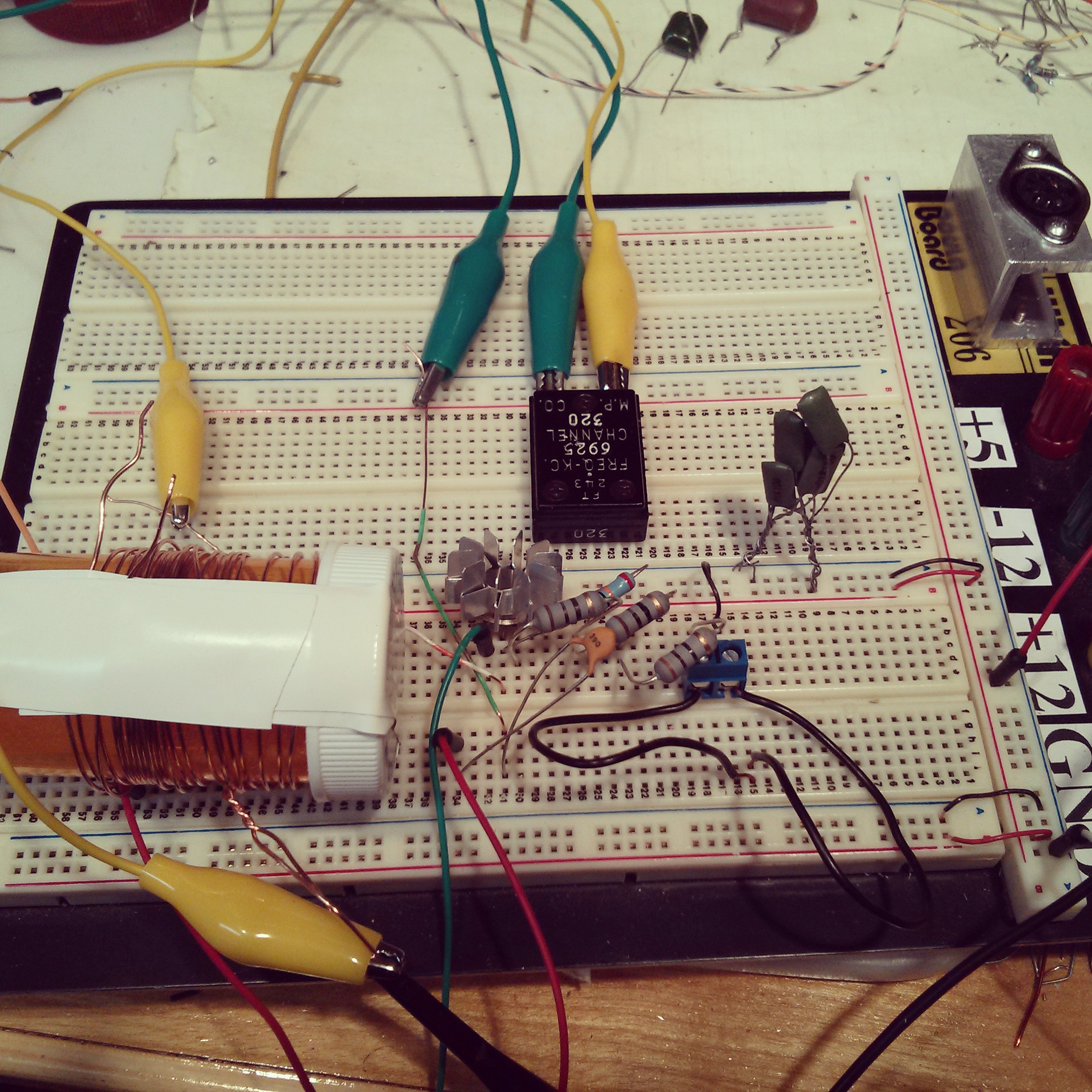
And of the completed design:
I constructed the circuit for 40m, and get almost 3/4 of a watt out of it with a 12v supply! Â That's pretty decent for such a simple circuit.
Now for the bad; this transmitter has one very unfortunate side effect, harmonics. Â If you want to really use this circuit on the air, you will need to add a low pass filter.
I will cover creating a low pass filter in my next installment, and later discuss adding an audio modulator to turn it into a shortwave pirate transmitter, if you are into that sort of thing.
Posted: Jul 31, 2013
Keyword tags: shortwavetransmitterqrpelectronicsschematic

