

A Better Amplified Crystal Oscillator Transmitter
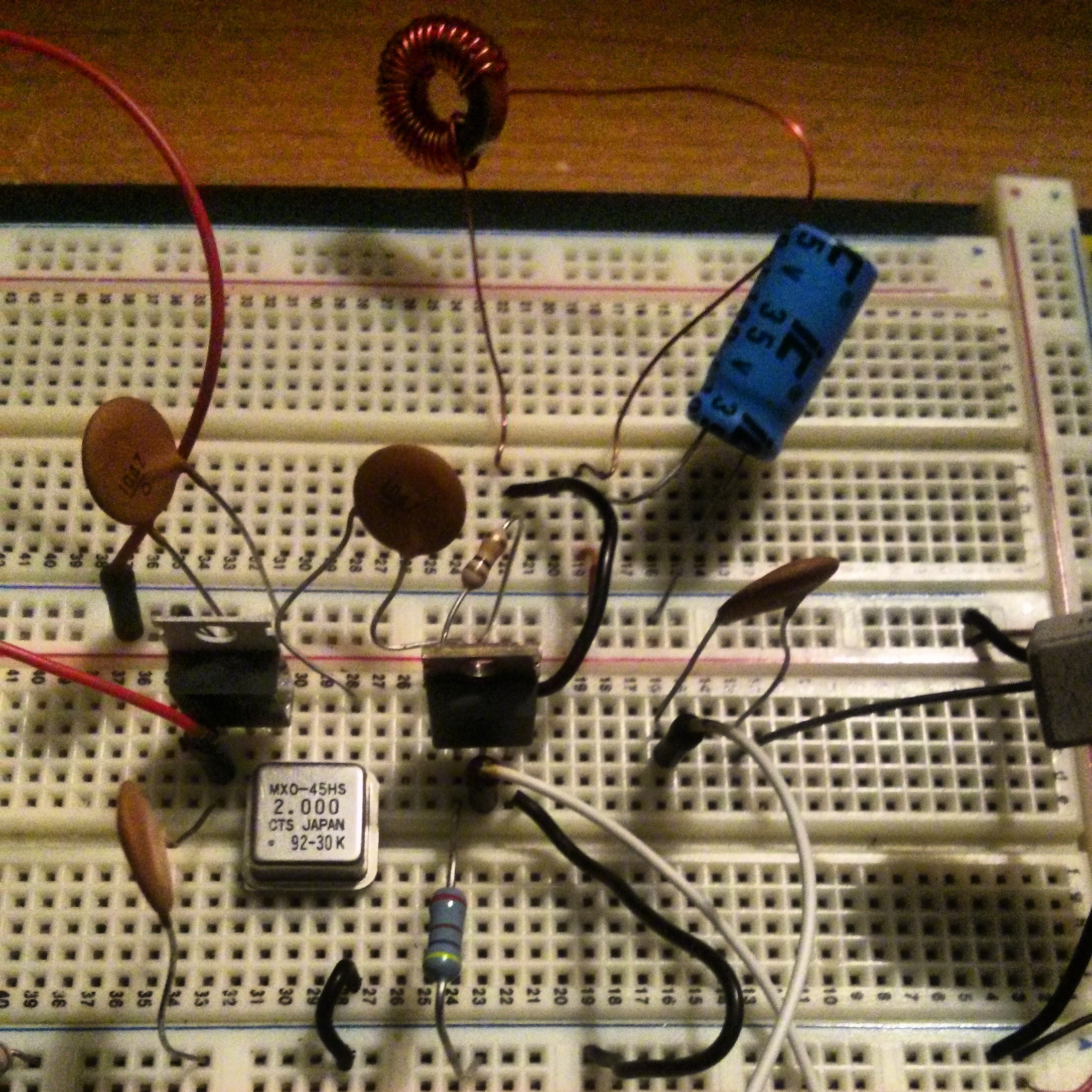
A couple months ago I posted a design for a bare bones amplified crystal oscillator transmitter. Â It turns out that it was a little too bare bones, and was in need of some improvement. Â After posting it online, I received some helpful feedback from the friendly folks at HF Underground, that pointed me in the right direction to brush up the design.I present an improved design for a crystal oscillator amplifier:

If you haven't read my initial post, take a quick read, then head back here and read on.
The modifications are as follows:
1) C1, C2, & C3 have been added for capacitive filtering for the supply voltage and output waveform of the oscillator stage.
2) R1 and R2 have been added as a bias for Q1.
When I was initially tinkering with this circuit, it bothered me that I didn't include a resistor for the IRF510 bias. Â When I added in a bias resistor the amplified signal was lost, so I got rid of it. Â In general, a bad idea. Â It turns out that if I spent some extra time reading the data sheet I would have noticed that the gate voltage bias for the IRF510 should be between 2 - 4v.
R1 and R2 set up in this fashion create a voltage divider, which gets us to the voltage range required. Â R2 can be anything between 2k - 5k ohms. Â While experimenting, I used a 10k potentiometer as R2, to see what the optimal value might be. Â If R2 is around 3.4k ohms, you can squeeze a little more power out of this circuit, which likely means that the IRF510 is optimal with a gate bias voltage around 3v. Â I ended up using the 4.7k ohm resistor, because I thought the wave form looked a little cleaner on the scope.
The biasing also prevents Q1 from getting quite as hot as it did previously. Â But, it still does heat up, and definitely needs a heat sink.
3) C5 has been reduced to 0.1uF. Â Larger capacitor values here do not change the behavior of the circuit anymore.
I make regular ham radio contacts hundreds of miles away with my QRP transceiver using 5 watts or less, so you can get an idea of how far these signals could reach on certain radio bands.
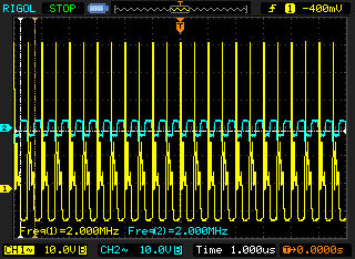
The above circuit measured on the oscilloscope.
Disclaimer
All the disclaimers I wrote in my original post still hold with this circuit. Â Even though this is an improved version of the transmitter, it is still extremely illegal to put on the air. Â The harmonics caused by the crystal oscillator and the power this circuit can generate will pollute a lot of RF space. Â The dummy load and low pass filter indicated in the schematic are not suggestions.This circuit can be made legal if the crystal oscillator (which outputs a square wave) is instead replaced with an oscillator stage that puts out a signal in a frequency you are legally allowed to operate on; most likely this also means you need a ham radio license to put it on the air. Â This is something that I will be exploring in an upcoming post.
Posted: Oct 30, 2014
Keyword tags: crystal oscillatortransmitteramplifierirf510schematic1 watt5 watts20 watts


Recent Posts
Sticky Posts
shortwavetransmitterqrpschematicAM transmitterelectronics500mWarrlfield daycwradio operatingdayton hamventionham radiocrystal radiosteampunkbasicsmatchbox radio1N34 dioderocket radiota7642mk484zn414AM radiomake a radio