

Teardown of 1980's era Wakie Talkies and Transistor Radio
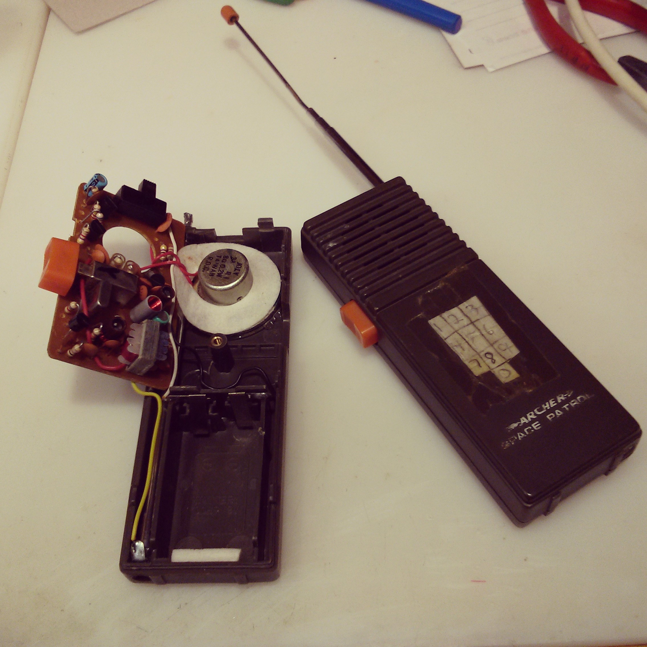
Rummaging through my parent's basement, I found a few radios I owned as a kid.  I was curious what was on the inside, so I took them apart to see what made them tick.First up is the Archer Space Patrol Wakie Talkie that Radio Shack sold in the 1980's.  These were great units.  Apart from using them on backyard detective missions, we used them as a family when cutting down Christmas trees.  I'm not sure of the range, but I believe they would go at least a few hundred feet.
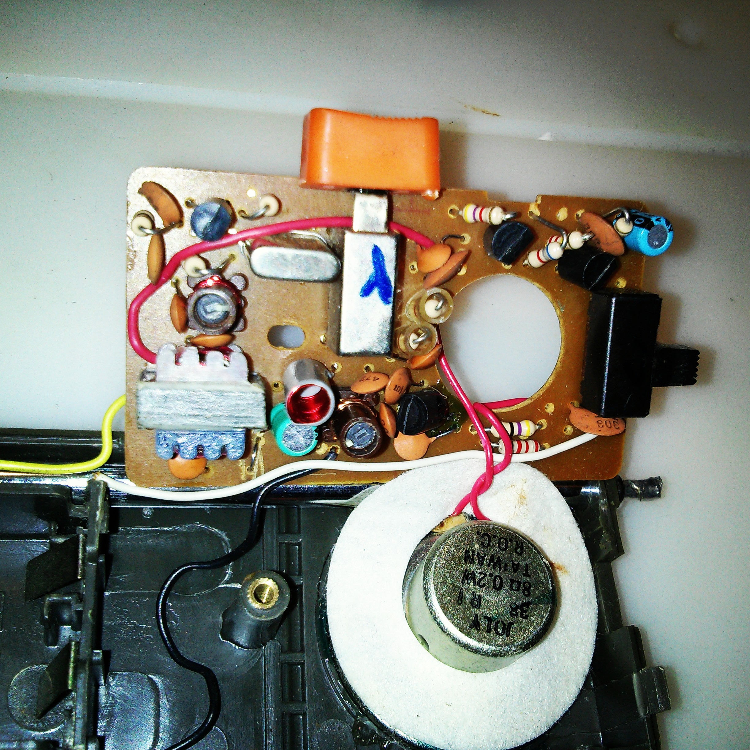
Looking inside, I was impressed that they were hand soldered. Â Actually, all the radios below were hand soldered. Â The radio circuit appears to be a pretty standard design. Â The heart is a 49.860 kHz crystal, which is also the frequency that it transmits an AM signal. Â You can also see a few inductor coils, a transformer, and 3 transistors used in each stage of the circuit.
I was able to find these two images online that appear to be the schematic for this radio or a similar model. Â Unfortunately, there doesn't seem to be any better quality images of the schematic available. Â The schematic images are courtesy of radiomuseum.org.
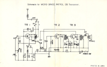
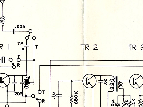
It's a little difficult to make out what's happening, but I believe one stage is for the transmit, one is for the receive, and the third for the oscillator.
EDIT 01/06/2016: Â Reader Kevin Ferguson wrote in to provide more insight into how these walkie talkies work:
"I can tell you a bit about how the walkie talkies worked. The circuitry is a wonder of economy. First off, all three transistor stages are used for both transmit and receive, as is most of the circuitry...including the speaker, which becomes the microphone. The leftmost transistor is the power oscillator on transmit. On receive the crystal is disconnected, and it becomes a regenerative RF amplifier/detector. On receive, the detector drives two stages of Audio amplification which feeds the speaker. On transmit, the input of the audio amp is moved from the detector to the speaker (which is used as a microphone, recall) The oscillator power is disconnected from the battery and connected to the output of the audio amplifier, which creates AM modulates the oscillator. The PTT switch is very busy, as the following must be switched: -Crystal -Antenna -speaker -audio amp output So that push-to-talk switch is a 4 pole double throw job."
Here's what the inside looks like:
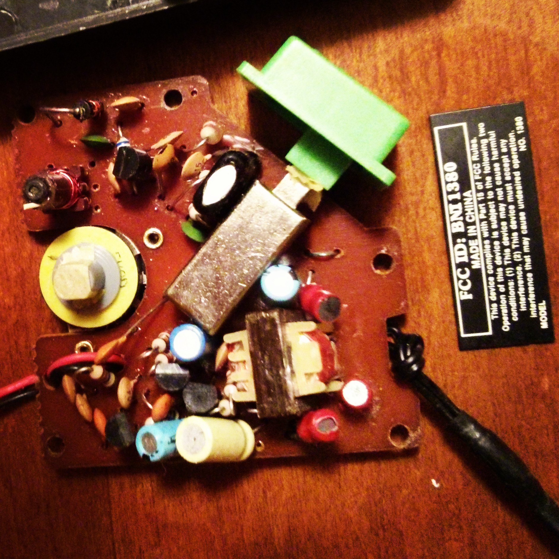
Next up is the Spy Tech Walkie Talkie set.
The inside of this is very similar to the Archer model. Â I couldn't find a schematic for this one, but looking at it we see a lot of the same parts, and the same 49.860 kHz crystal. Â I'm not sure if these two could communicate with each other or not. Â Both units are barely working, but I was able to pick up the AM carrier wave on each.
The reason these were cool was the earpiece and microphone that could clip on a shirt, making the unit concealable for backyard spy missions. Â If my memory serves me, the range on these units weren't all that great. Â I believe the wires used for the microphone and ear piece doubles as the antenna, since there is no other obvious antenna in the unit.
Here's what's on the inside:

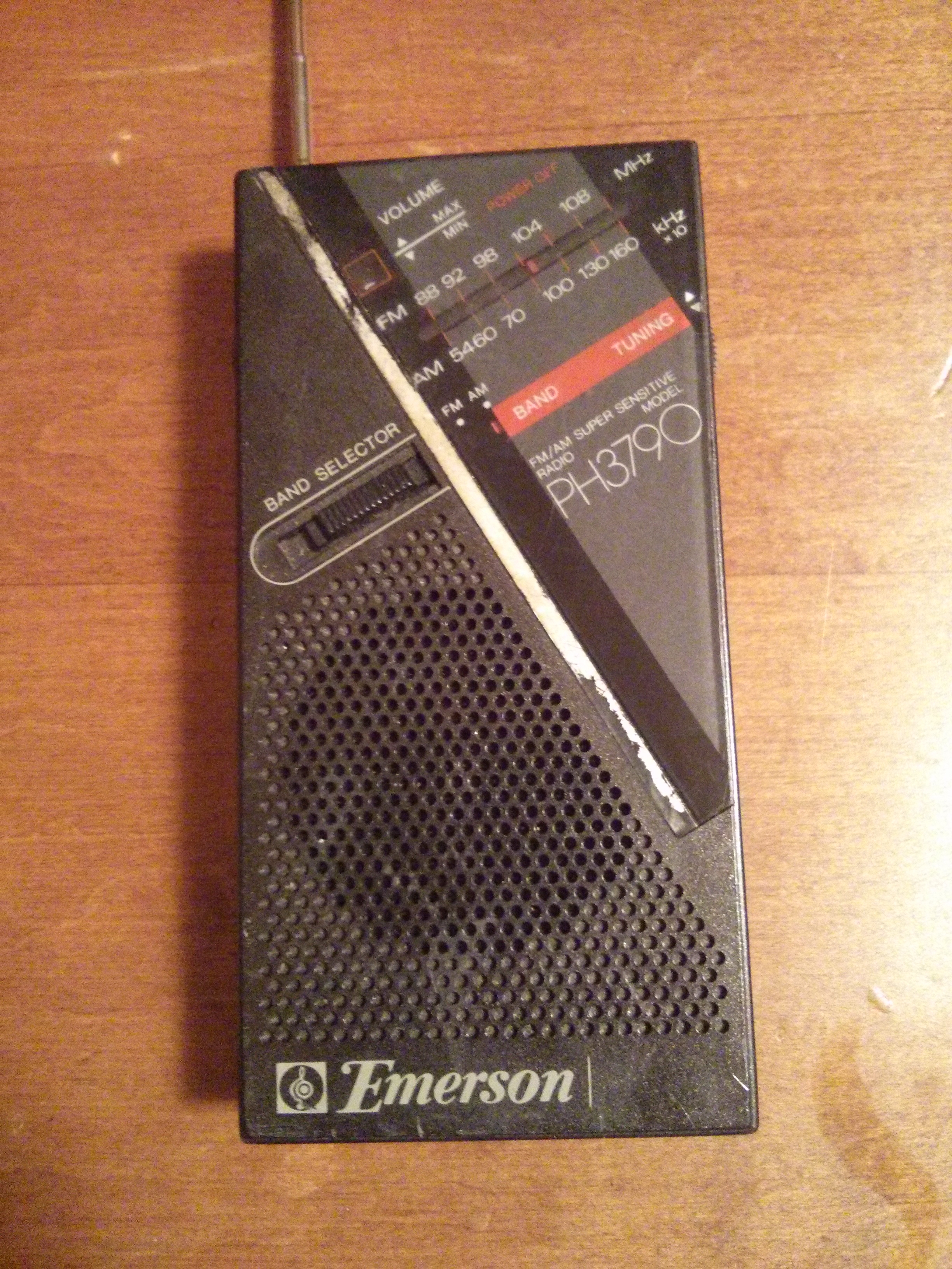
Lastly, is an Emerson AM/FM transistor radio. Â This was a great little radio, and I spent many hours as a kid tuning around the AM dial at night to see what I could pick up.
The unit is still in good condition, but the FM receive isn't working. Â I think it's because the switch went bad to choose between the two bands. Â AM reception is still great, and I was able to pick up a Canadian AM station loud and clear from New Jersey, which is a testament to its advertised "super sensitive" tuning.
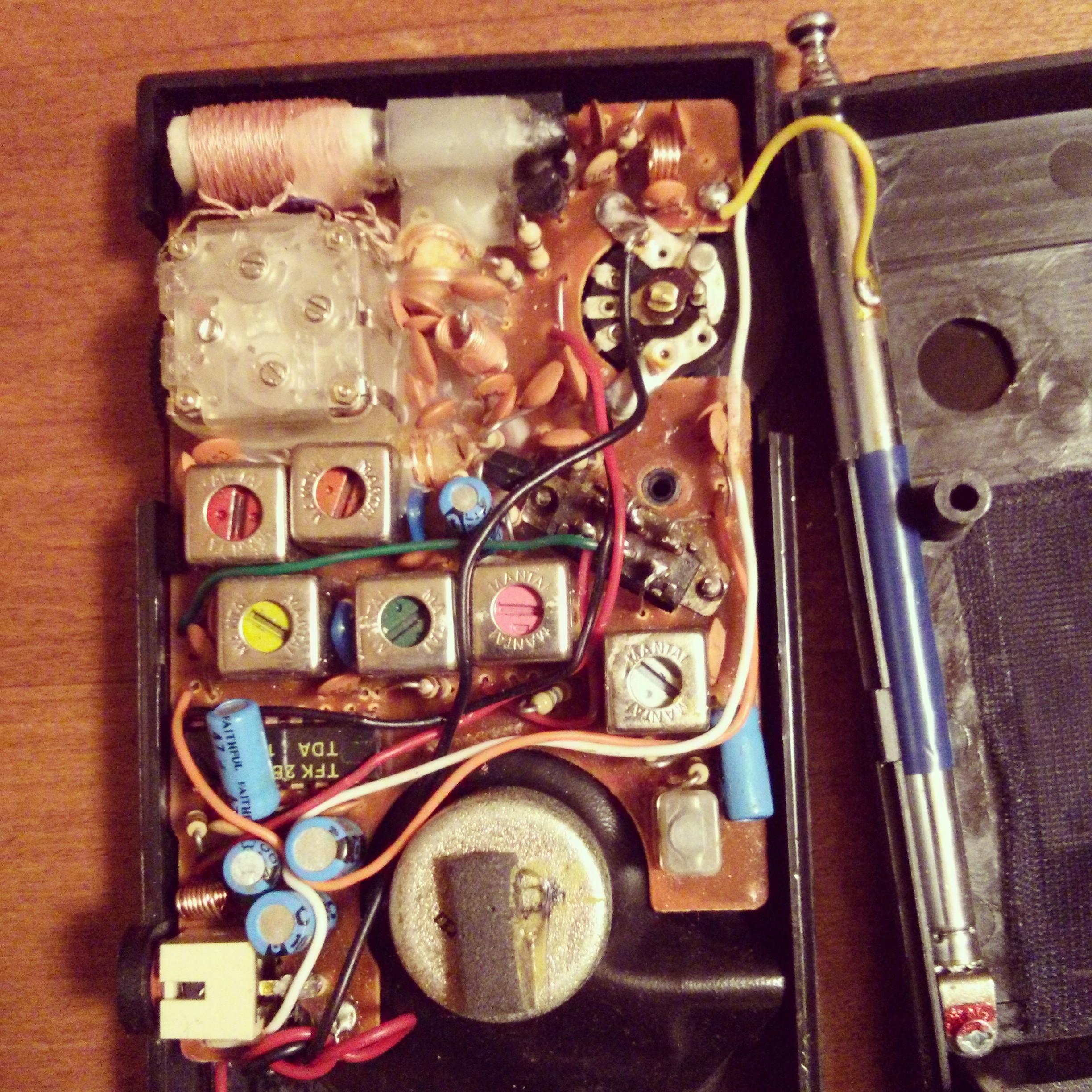
The design of this radio is a bit more complex, and appears to be a superhetrodyne.  Inside you can see a several inductors.  The large coil is for AM band reception.  There are also several tunable coils that act as intermediate frequency stages (also known as IF stages), which are used to process the signals.
Here's a couple pictures of the radio inside and out:
Posted: Jul 22, 2013
Keyword tags: teardownwalkie talkieradioelectronics


Recent Posts
Sticky Posts
shortwavetransmitterqrpschematicAM transmitterelectronics500mWarrlfield daycwradio operatingdayton hamventionham radiocrystal radiosteampunkbasicsmatchbox radio1N34 dioderocket radiota7642mk484zn414AM radiomake a radio