

An Altoids Tin Low Pass Filter For Shortwave Transmitters
In my last post, the Michigan Mighty Mite was discussed; a very simple shortwave transmitter that puts out about a half a watt on several HF bands. Â The biggest problem with its simple design is that it outputs harmonics which should be filtered out.
I briefly discussed harmonics in my post on crystal oscillators. Â Crystal oscillators produce a square wave, which will produce odd harmonics. Â The Michigan Mighty Mite does produce a sine wave, and in theory a perfect sine wave won't produce any harmonics. Â In practice though, it's very difficult to tune this circuit to produce an absolutely perfect sine wave, and thus harmonics will be produced.
Luckily, it's relatively simple to filter out the harmonics you wish to eliminate with a low pass filter!
A low pass filter is essentially a LC circuit in a pi-network configuration.  By choosing the correct inductor and capacitor values, you can configure the network to drop frequencies higher than a specified value.
These are the best two resources I've found on the web pertaining to low pass RF filters:
- George Dobbs, G3RJV, A Short Guide to Harmonic Filters for QRP Transmitter Output. Â This is an awesome article, which lays out practical filter designs that work on a variety of shortwave bands. Â It also describes the best ferrite toroid values and wire gauges to use for creating inductors.
- This website by WA4DSYÂ automatically calculates the correct LC values for a filter by specifying the cutoff frequency, which will allow you to create a filter for practically any cutoff value. Â It also gives options for three different filter types: Butterworth, Chebyshev, and Bessel, as well as configurations for both high and low impedance filters, and a chart of the db drop off. Â Excellent!
Making a Low Pass RF Filter
Since I designed my Michigan Mighty Mite for the 40 meter band, I'm using G3RJV's design for 7.0 MHz filter. Â This design has a 3db cutoff frequency of 7.36 MHz and a 30db cutoff at 9.04 MHz. Â This should really dampen any spurious signals, since our first harmonic would be at around 14 MHz. Â This is a 7 pole filter (one pole for each part -- 4 capacitors and 3 inductors). Â The more poles, the deeper the cutoff will be, meaning the filter will act more efficiently. Â Try out WA4DSY's calculator using different pole configurations. Â You can see how the cutoff changes deeper the more poles included.
G3RJV doesn't specify the filter type in his article, but plugging the data into WA4DSY's calculator, the values he chose look most like a Butterworth configuration, so we can expect the db drop off similar to that chart.
This is the schematic for a low pass filter for 40 meters or for frequencies around 7 MHz: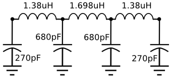
There is a good chance you won't have any inductors or capacitors of the exact values specified handy; so, you need to make your own.
The capacitor values are simple. Â If you didn't already know, putting capacitors in parallel will add their values. Â So, for the two 270pF capacitors, I used the combination: 100pF + 100pF + 47pF + 22pF = 269pF. Â Close enough. Â For the 680pF I used: 470pF + 100pF + 100pF + 10pF = 680pF. Â Dead on! Â It's recommended to use either mylar or ceramic capacitors for filters.
For the inductors, you will need three T37-6 ferrite toroids and some 26 gauge magnet wire.  If you don't have any T37-6 ferrite toroids, check out the links I posted here.  You will want to wind two of them to 21 turns and one to 24 turns.
Also I should note, you could use different value toroids.  What's important is the final inductance, not how it's made.  If you use a different toroid, calculate or look up the correct number of turns to achieve the desired inductance.  I will cover winding toroids and inductance further in a future post.  For now, just make sure you evenly space the windings around the toroid, and leave a bit of space between the two sides.  To strip the ends of the magnet wire, I usually use a lighter to burn the ends and use an x-acto knife to scrape the wire bare.
I initially laid the circuit out on a breadboard and was not achieving good results. Â The reason being, breadboards connections can add extra capacitance into a circuit. Â Whatever was happening was enough to throw my results off.
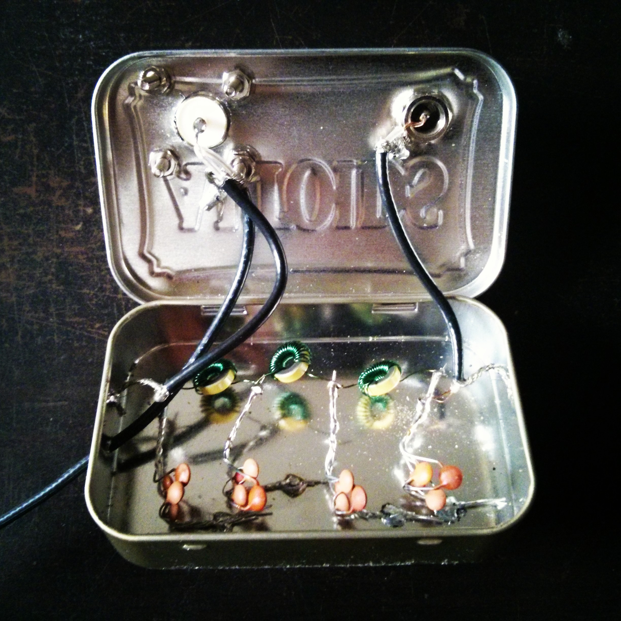
So instead, I chose to solder up the final circuit inside an Altoids tin, using dead bug style construction. Â I included SO-239 and PL-256 coax connectors, and used RG-174/u 50 ohm coax for the connectors. Â I also included a short length of coax from the side of the tin, as my Michigan Mighty Mite uses screw connectors to connect to the antenna.
This is the final result: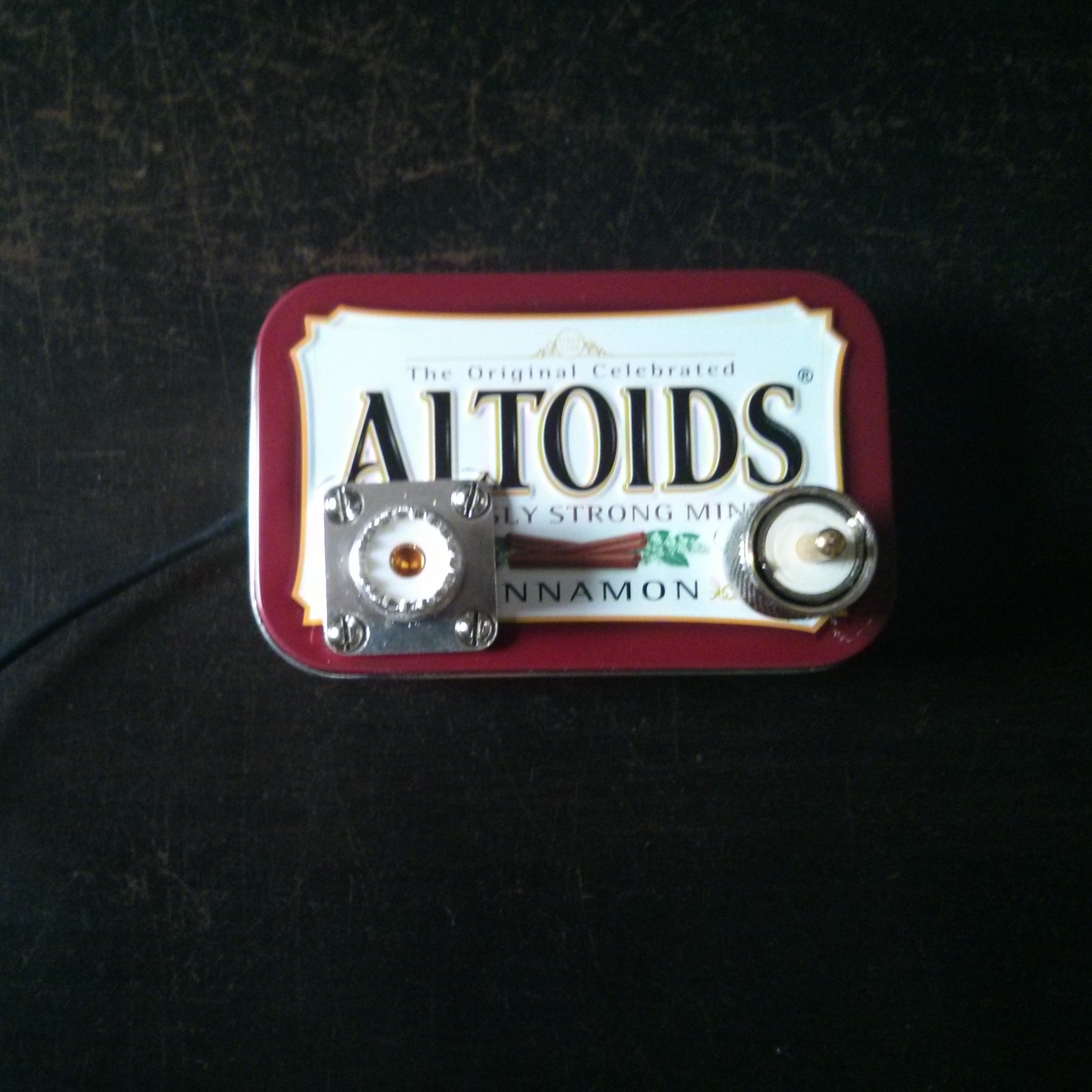
The best way to test the results of the filter is to use a spectrum analyzer. Â I don't own one or have access to one. Â In general they can be quite expensive. Â I did hook up the filter to my Michigan Mighty Mite, and saw that the RF watts output was the same as it was previously. Â It should output the same power for the transmit frequency and dampen power for higher signals. Â So, looking at that result and trusting in the physics at play here, I'm satisfied things are working properly.
Why filter out harmonics?
Simply put, it's good operating practice to filter out harmonics. Â If you are a radio amateur, you are only legally allowed to transmit on certain bands. Â If you are operating a transmitter throwing out harmonics, you may be unintentionally polluting the airwaves with your signal in places you never expected to hear it. Â Even if you flaunt FCC regulation and broadcast a pirate signal, remember that the airwaves are shared by commercial broadcasters, police, fire, EMS, and others, so it's important to filter out everything other than the desired broadcast frequency.
Posted: Aug 10, 2013
Keyword tags: altoidsfiltershortwaveHFtransmitterlow pass filter

